|
Obsolete Outboards |

|
| by
Max Wawrzyniak - St Louis, Missouri - USA
Bringing
a 1956 Johnson 15 hp Back to Life
Part
VI: Reinstalling
the Magneto and Carb |
 |
Part
1 - Part
2 - Part 3 - Part
4 - Part 5 - Part
7
When we last visited the 1956 Johnson 15, the carb
had been cleaned and assembled with a rebuild kit,
and the magneto had been assembled with new ignition
points and condensers, and also new spark plug wires
and/or coils if those had been required. Time to reinstall
these (2) major components onto the motor itself.
The carburetor is reattached to the intake manifold
using the (2) studs and nuts that bolt through it's
flange. There was an old gasket between the carb and
the manifold that probably could be reused, but your
rebuild kit will have a new gasket. In fact, you will
probably find that your rebuild kit has SEVERAL new
gaskets, all of which are similar except that the
diameter of the big center hole is different in each
one. Match up your old gasket to one of the new ones,
or if you no longer have the old gasket, use the new
one with a center hole of about the same diameter
as the carb throat diameter. The reason for all the
different gaskets is that the same rebuild kit can
be used for several different engines and so extra
parts are included. If you don't have a new gasket
you can reuse the old one if it is in good condition.
I used to smear a bit of gasket sealer on old carb
mounting gaskets but I don't bother anymore. The nuts
on the carb mounting studs should be torqued (tightened)
to a specific inch-pounds specification, but since
you are not going to bother with a torque wrench just
get them pretty tight without twisting the darn things
off. You are dealing with soft aluminum castings here
so don't overdo it.
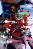 |
The new
carburetor-mounting gasket is in place
and the new fuel hoses are being installed.
Note the "follower". On the
larger engines it is usually a rubber
roller; smaller engines use just a piece
of round bar (no roller).
(click
images to enlarge) |
|
Once the carb is bolted on, it is time to run the
new fuel hoses. There is special marine- grade fuel
hose available and it is good stuff. There is also
common automotive-grade fuel hose available at auto
parts stores, and it is cheaper. I use the auto. grade
hose and have yet to have any problems. I am not recommending
that you use what I use: you are responsible for your
own actions and decisions. I also like to use clear
hose because it allows one to see what is going on
with the fuel system, but genuine clear fuel hose
is rather expensive. If you try using the cheap clear
vinyl hose available at many hardware stores you will
find that is hardens with exposure to fuel and is
only good for a few months: I recommend against using
it.
An outboard motor that uses a pressure tank will have
(2) hoses clamped to the quick connect fitting on
the motor. The hose attached to the hose barb on the
fitting marked "air" goes to the hose nipple
on the intake manifold below the carb. The hose that
attaches to the hose barb on the fitting marked "fuel"
attaches to the hose barb on the carburetor bowl.
Pretty simple. Use good hose clamps; the ones that
came with the engines were simple little wire "squeeze"
types that are a pain in the butt to remove and replace.
See if you can get some tiny little worm-screw hose
clamps at the auto parts store when you pick-up the
auto-grade fuel hose (yeh, like I really thought you
would buy the marine hose.) There are also plastic
"one-use-only" clamps available, but in
order to remove them you have to cut them, so they
are not reusable and you had better get spares.
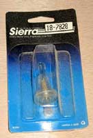
The Sierra
"in-line" filter that I usually
use. Made for use with 1/4 inch hose, it
can be made to work with smaller diameter
hose, but a better choice would be a filter
of the correct size.
|
|
|
Some really, really cheap individuals have been
known to clamp fuel hoses with ordinary plastic wire-ties.
These do not work well and are definitely not recommended.
Engines fitted with fuel pumps are a little more complicated
to "plumb" but still not a big deal. The
quick connect fitting has a single hose barb; the
hose from the fitting connects to the intake side
of the fuel pump (the pump will be marked in some
manner.) A hose is then run from the output side of
the pump to the carburetor. If your fuel pump is direct-mounted
to the transfer port cover of the engine, then that
is all there is to it. If, however, you are using
a pump that receives it's pressure-vacuum pulsations
through a hose, such as was used in the fuel pump
conversion column, you will also need to run the pressure/vacuum
hose. You can probably use the same hose but keep
this in mind: in the pressure tank engines all hoses
are under pressure, while on a fuel pump engine the
supply hose to the pump is under vacuum; the discharge
hose from the pump is under pressure, and the hose
supplying pressure/vacuum to the pump (if a hose is
used) is alternately under pressure and vacuum. Make
sure that the hose you use in a vacuum application
can handle the vacuum without collapsing.
 |
Instructions
for synchronizing the magneto advance
to the carburetor throttle butterfly valve.
Note the comment that the choke needs
to be in the "off" position
while making this adjustment.
|
|
Most of these old OMC outboards were fitted with
a fuel strainer and a glass sediment bowl. Sometimes
the strainer/bowl is an integral part of the carb
and sometimes it is a separately-mounted component.
If separately mounted, be sure to include the strainer
in your fuel line. It is probably best to route the
hoses so that the strainer is under pressure (on the
discharge side of the fuel pump) instead of under
vacuum (on the intake side of the fuel pump). If the
strainer is part of the carb, it will be under pressure
and you don't have to worry about running a hose to
it. Of course, no matter where the strainer is on
a pressure tank engine it is under pressure. Your
rebuild kit kit should have a new gasket for the glass
strainer bowl. The actual strainer element within
the bowl is sintered bronze or something like that
and is cleanable and reusable. Give it a good spraying
with your can of carb cleaner (use eye protection.)
I also like to use a small "in line" fuel
filter in addition to the original-equipment fuel
strainer. The Sierra brand 18-7828 filter is compact
and made of clear plastic (so that you can see what
is going on) and is the filter that I always use.
It is for 1/4 inch hose, but I use it on small er
hoses by either dipping the end of the hose in boiling
water for a moment in order to soften the hose enough
to slip the hose onto the hose barbs, or I just put
a drop of oil on the hose barbs and force the hose
on. The hose I use has been able to stand up to this
mistreatment but cheap hose may split. I leave any
hose that forced onto the filter a bit long so that
a half-inch or so can be cut-off when a new filter
is installed. I also always install the in-line filter
on the discharge side of the fuel pump on those outboards
so equipped, so that the filter is under pressure
and not vacuum. Note that most of these filters have
an arrow on them indicating the direction in which
fuel should flow through the filter.
Again, use good hose clamps. While a leak under
pressure will be obvious, a vacuum leak in the fuel
system of a fuel pump-equipped engine can be a frustrating
problem to trouble-shoot. Use new hoses and good clamps
and head-off any vacuum problems. Vacuum leaks suck
(sorry).
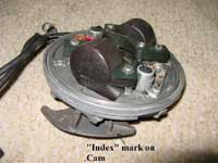
The index
mark on the cam. On this magneto it is a
line, but on some others it is a tiny arrow.
|
|
|
With the carb bolted on and the hoses installed,
you can now install the magneto. Set the mageto down
over the crankshaft while being sure that you have
the front of the magneto to the front of the engine.
The sheet metal "ramp" or "cam"
should be over the carb. It will be necessary for
you to hold the ignition points in the "open"
position so that the spring-loaded arms will clear
the cam on the crankshaft that the arms ride on. Take
your time. The four screws that hold the magneto on
need to be lined-up properly with the holes in the
metal ring under the magneto. Make sure you are not
pinching the spark plug wires. Once screwed-down,
the magneto should rotate back and forth smoothly:
this is how the "spark" is advanced. Re-attach
the little bellcrank (lever) on the Port side of the
motor that connects the twist-grip throttle to the
magneto.
You are now ready to "synchronize" the
magneto to the carb. When you twist the "twist
grip" on the tiller, the magneto rotates back
and forth. There is a linkage from the carburetor
"butterfly" throttle valve that has a "follower"
(either a rubber roller or just a piece of round bar)
that rides along that cam on the magneto. As the magneto
rotates, the follower rides up the incline on that
cam and in turn opens the carb. throttle butterfly
valve. In order for the engine to run properly, the
butterfly needs to open at the correct time. The cam
is attached to the bottom of the magneto with two
small screws, one of which has a slotted (oversized)
hole. The cam will also have an index mark, either
a line or an arrow, on it's upper face. Loosen (but
do not remove) the (2) screws holding the cam, and
adjust the position of the cam so that the carb butterfly
starts to open at the instant that the follower is
aligned with the mark on the cam. Keep in mind that
there is a bit of "slack" or looseness in
the linkage that couples the follower to the butterfly
shaft: the slack should be all "taken-up"
and the butterfly shaft itself should just start to
rotate when the follower is aligned with the mark
on the cam. Then tighten the cam mounting screws and
re-check to be sure nothing has changed.
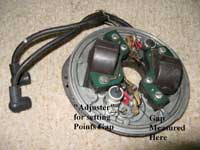 |
The "adjuster"
for setting the gap looks like a screw
but it is not. It is permanently attached
to the magneto. The adjuster is rotated
back and forth to adjust the size of the
points gap. Very very VERY tiny movements
of the adjuster make a big difference
in the point gap. |
|
It is now time to "set the points." What
you are going to do is to adjust how far the ignition
points open. OMC (Outboard Marine Corp, the manufacturer
of Johnson, Evinrude, & Gale outboards) made special
timing tools which were used in conjunction with a
test light for this purpose and I have a set of those
tools but never use them. What I use is a set of "feeler
gauges," available at a cost of a couple bucks
at any auto parts store or most discount stores. You
will need one with leaves measuring .018, .020, &
.022 inches in thickness. All feeler gauge sets that
I have ever seen have these sizes so that other than
avoiding a metric set (unless you want to make the
conversion) you don't really need to buy anything
but the cheapest set you can find.
The rocker arms of the ignition points ride on a
cam on the crankshaft, As the crankshaft spins, the
lobe of the cam opens and closes the points. Roll
the crankshaft around by hand until the tiny plastic
rubbing block on the rocker arm of one of the points
sets is aligned with the key (The metal thing that
locks the cam and the flywheel to the crankshaft so
that they don't spin loosely on the crankshaft.).
I usually remove the spark plugs (assuming they are
not already out), put the engine into forward gear,
and roll the engine around with my foot on the propeller.
Or, you can thread the crankshaft nut down onto the
crankshaft and use a wrench to rotate the crankshaft.
Slightly loosen the single mounting screw on the points
set base plate, and then slowly rotate the adjuster
back and forth while holding the .020 leaf of your
feeler gauge in between the contact surfaces of the
points. You want to feel a very slight "drag"
when inserting and removing the .020 leaf into the
gap. Pushing the .020 leaf in should not spread the
points open even a minute amount, nor should the leaf
"rattle" back and forth between the points
contacts (even a tiny amount.) You want a barely perceptible"drag."
When you have that, tighten the mounting screw and
check it again to see if the setting changed any (
it probably did, and you will probably have to re-do
this two or three times before you end-up with the
barely perceptible drag after tightening the mounting
screw). The tighter you can leave the mounting screw
while making your adjustments, the less likely the
setting is to change when the screw is finally tightened.
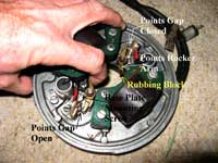 Using
my finger to hold the contact surfaces of
the points open; you will be using your
feeler gauge between these (2) surfaces.
This is also how you hold the rocker arms
back when installing the magneto on the
engine. The points are spring-loaded to
the closed position. Note the rubbing block
that rides on the cam on the crankshaft. Using
my finger to hold the contact surfaces of
the points open; you will be using your
feeler gauge between these (2) surfaces.
This is also how you hold the rocker arms
back when installing the magneto on the
engine. The points are spring-loaded to
the closed position. Note the rubbing block
that rides on the cam on the crankshaft. |
|
If you have the mounting screw tightened and you
are happy with the "drag," then try inserting
the .018 leaf into the points gap: it should "rattle"
back and forth a tiny amount. And when you try inserting
the .022 leaf it should be necessary to slightly force
the leaf into the gap.
Now rotate the crankshaft 180 degrees until the key
on the crankshaft is lined-up with the rubbing block
on the rocker arm on the other set of points and go
through the whole process of setting the other points,
Then rotate the crankshaft until the key is again
aligned with the rubbing block on the first set of
points and check it again. Then check the second set
of points again.
Perhaps more critical than the exact gap of the points
is that both sets of points be set as exactly alike
as possible. OMC said that new points sets could be
set @ .018 if desired while .020 was recommended for
setting the gaps of existing points; I set all of
mine to .020 whether I have just installed new points
or are adjusting old ones.
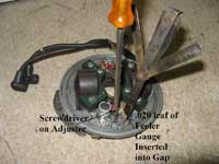 |
Using
a screwdriver to make tiny TINY movements
on the adjuster while checking the gap
with the .020 leaf of the feeler gauge. |
|
Finally those little cyanide capsules I mentioned
way back months ago? They contain a bit of grease.
The purpose of the grease is to lubricate the rubbing
blocks on the points rocker arms so that the plastic
rubbing blocks do not wear excessively which would
change the gap setting of the points. You engine originally
came with a little felt wiper which rode on the cam;
if you wish you can apply a drop or so of grease to
that wiper. Often ,however, the wiper felt is missing.
I have never applied this grease to any of the engines
I have ever worked on. Every few years I give them
a tune-up which would include at least a gap re-setting
which may be why I never have a problem with rubbing
block wear changing the point gap. It's up to you.
You can apply the grease (very sparingly) if you wish,
or you can "toss" the cyanide capsules and
not worry about it. I don't know too many people who
run their outboards enough hours to make rubbing block
wear a serious concern. Again, use VERY little grease
if you use it: grease spun-off the spinning cam can
raise havoc if it gets on the contact surfaces of
the ignition points. I once spent a considerable amount
of time trying to trouble-shoot an outboard that would
run good at idle speed, but as I advanced the throttle,
if would stumble and cough and hardly speed-up at
all until I got to full-thottle, at which point the
thing would suddenly "wind-up" and about
throw me out of the boat. After much time spent cleaning
and rebuilding the carb and adjusting the gaps of
the existing points, I finally discovered a tiny drop
of grease/oil on one set of points, Replacing both
sets of points had the engine running like new.
Next time we reinstall the flywheel and see if the
darn thing will run.
Happy Motor'n
Later,
Max

click here for a
list of Columns by Max Wawrzyniak
|