|
One-Sheet
Baby Canoe Part 2 |
| By Gaetan
Jette - Sherbrooke, Canada |
Part
1 - Part 2 - Part
3 - Part
4
Construction
Begins
I took many photos during the building
phase, but I did not write down a log. I'll try to
comment the building as best as I can remember. This
will be a detailed account, too detailed perhaps for
those who have already built a few boats. But since
this will be mostly a pictorial essay, it will be
easy for readers to skip what is old news for them
and concentrate on the more interesting details (I
hope). Now, I am a novice boatbuilder and I am not
a highly skilled or experienced woodworker either.
I do not claim this is the best way to build a boat,
it's just how I managed to do it.
Here is the lumber material list for
this project:
| Description |
Quantity |
Use |
| Plywood, 1/8 in. thick, 4 ft.
by 8 ft. |
1 |
Hull and paddle blades |
| 2 x 4 lumber, 8ft. long |
4 |
Backbone and center frame,
seat mold |
| 2 x 6, 12 ft. long |
1 |
Inwales, outwales |
| 1 x 4 plank, 8 ft. long, softwood |
2 |
Keel and other stuff |
| 1 x 4 plank, 8 ft. long, hardwood
* |
1 |
Paddle shaft cutting jig |
| 1 x 2 pine, 8ft. long |
1 |
Edge of center frame |
| Waferboard, 1/2 inch thick,
4 ft. by 8 ft. |
1 |
Support for keel assembly, plywood
marking; patterns for paddle blades, center frame |
* or any plank with sharp, square
edges
 |
I used marine
grade plywood, but a cheaper luan ply might
do. The few luan samples at the local lumberyard
were not in good enough condition for the job.
The epoxy gallon I purchased was more expensive
than the plywood anyway. |
 |
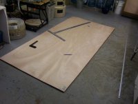
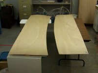
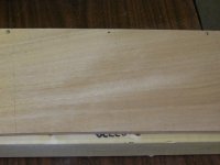
Lines are scribed
across the width of the sheet, six inches apart.
A drywall T-square proves handy for that. Then
all dots for one side of the boat are marked.
The arrows on the top and middle planks indicate
where are the bow and the top: these 2 planks
are not symmetrical. |
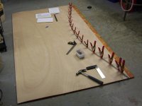 |
With the waferboard
used as a backing, nails are driven in the plywood.
I used an aluminum flat bar as a batten to trace
the patterns. |
 |
A flexible plastic
ruler is used for tracing the sharpest bends.
|
 |
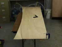
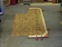
The bottom plank
is traced right at the edge of the sheet. Nails
just outside the plywood, wrapped with electric
tape, allow to keep the curve fair as it moves
away from the edge. |
 |
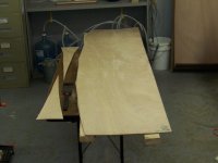
A "rough" cut
is made to split the sheet in two, but that
cut must be done as close to the line as possible,
due to a very tight spacing between planks.
The gap along the center of the sheet is under
a quarter inch wide. |
 |
 |
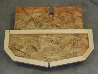
The
two halves are clamped together and the area
used for the breasthooks is cut off. |
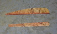 |
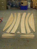
Tracing the patterns
for 4 paddle half-blades (top) and 4 cover plates
(bottom) is made easier by cutting patterns
in the waferboard. |
 |
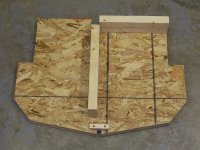 |
Here
is the center frame. 1 x 2 pine is screwed along
the edge. The notch at the bottom is where the
keel will be fitted. The notch at the top is for
the off-center backbone. |
 |
The parts for
the keel are dry fitted. You can see that all
the patterns were cut on one side of the waferboard
sheet, leaving the full length available for
the keel assembly. |
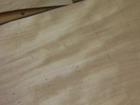 |
Because this
boat is built with a keel, I chose to mark and
pre-drill all the stitching holes before assembly.
|
 |
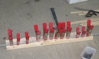
A few machine
screws are placed in the stitching holes to
keep the 2 plywood layers clamped together.
Each part is rough cut with a hand saw and then
a coarse metal file is used to trim down to
the scribed lines. Not the fastest way to do
it, but I find it too difficult to control a
circular saw freehand. |
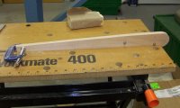 |
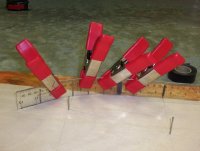
My Workmate proved
handy when dealing with smaller parts like the
paddle cover plates shown here. |
 |
One sheet, one
boat. Some assembly required... |
 |
Moving to boatyard
number 2. This project would never have happened
without my brother letting me use his utility
shed. This is where I spent most of my spare
time that summer. |
 |
The keel is assembled
with loose tongue and grove joints. The tongues
are cut from the leftover plywood strips. The
grooves are cut on a table saw, just one saw
kerf wide. This was a bit tight however, so
some sanding was required for the tongues to
fit. The parts are screwed down on the waferboard;
a plastic film prevents the parts from gluing
to it. |
Unfortunately, my first epoxy batch
didn't cure. After one week, I had to disassemble,
scrape and clean everything and start all over. Fortunately,
this was also my last batch that didn't cure.
 |
The keel curves
are scribed the same way as the plywood sheet
was. |
 |
The sharpest
bends require more nails. You can see here the
tongues in the joints. |
 |
The keel is cut
and the edges are routed with a quarter-inch
radius bit. |
 |
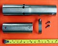
The stems are
left longer in order to screw them to the backbone.
The wide stem with all those holes you see here
didn't prove to be such a good idea when dealing
with the epoxy fillets inside. |
 |
The keel, center
frame and backbone are screwed together. The
2 x 4s at each end allow to the whole assembly
to rest on sawhorses, either right side up or
upside down. |
 |
The frame has
to be braced in every possible direction. |
 |
The top planks
are attached with screws to the center frame,
while the ends are attached with plastic ties
to the stems. |
Some stitch and glue designs use no frame
during construction, as described in Sam Devlin's
book "Devlin's Boat building" (at least for small
boats). Some designs use quite a few permanent frames,
like Phil Bolger's Cartopper. My design falls somewhere
in between, using a temporary center frame and a permanent
keel. I felt this would produce a straight hull with
little warp or twist, without having to build several
frames, and without some tricky alignment procedure.
As long as you glue the keel on a perfectly flat surface,
and that the 2x4s used for the backbone are straight,
the resulting hull should be straight enough.
 |
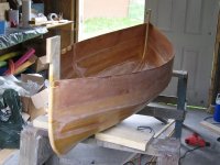
The middle planks
are attached next. |
 |
 |
The
bottom planks are attached to the middle planks
first. The keel and bottom planks are then attached
with plastic ties in one loop: for each hole
in the planks there is a pair of holes in the
keel. |
 |
A few screws
are necessary to force in place the ends of
the bottom and middle planks. Instead of pulling
the planks tight against the stems, the slim
plastic ties stretched under high tension. |
 |
A few screws,
backed by small plywood squares, are also needed
on the bottom chine near the bow and stern.
These plywood squares were also cut from the
leftover plywood strips. |
One mistake I made was to assume that
the 4-inch planks I bought were 3/4-inch thick. It
seems that construction grade planks are 11/16-inch
thick nowadays. Well at least in the area where I
live. The center frame was built for a 3/4-inch thick
keel. As a result, the edge of the bottom planks could
not be pulled tight against the keel, especially near
the center frame. This made it harder for the edge
to follow the fair curve of the keel. A few match-size
splinters, slipped under the plastic tie loops (on
the inside) helped maintain proper alignment along
the keel.
 |
Small splinters
are used to fair the keel side of the bottom
planks. This photo was out of focus so I sketched
over it. |
 |
The first epoxy
fillets are done on the inside of the keel.
They have to stop short of the center frame.
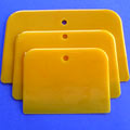
I used the round corner of a plastic spreader
to shape the fillet. 3-inch fiberglass tape
spreads over the keel and both fillets. |
 |
In order to achieve
fair curves along the chines, temporary outwales
were first screwed and clamped along the sheerline.
These temporary outwales will later become the
permanent inwales. |
 |
Epoxy fillets
have now been done on both chines inside. I
used the lid of a cottage cheese plastic container
(about 4-1/2 inches wide) to spread the epoxy
for the chine fillets. |
 |
Before starting
the epoxy work on the outside, I had first to
correct a mistake: I forgot to wrap the edge
of the frame with some plastic film. Luckily,
this is a small hull. Just a few screws to take
off and the problem was solved. |
Before doing the epoxy fillets on
the outside, the plastic ties are cut off first with
cutting pliers, then trimmed flush with a wood chisel.
 |
 |
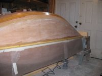
The
fiberglass tape has been done on the outside.
The tape on the keel covers the epoxy fillets
on both sides of the keel, more or less. It
had to be cut in sections near each end: the
sharp curve would have caused too much wrinkles.
|
 |
 |
The
fiberglass fabric is laid on the boat and cut
roughly to size, in two halves. I decided to
cover only the bottom planks, with some overlap
on the bottom chine and along the keel. It might
have worked better to unfold the fiberglass
fabric a few days in advance. The wrinkles of
each fold proved difficult to cover with a minimal
amount of epoxy. |
 |
Before the final
fairing along the stems, a notch is cut in the
stem where the outwale will rest. Lines are
scribed with a pencil, a sawcut is done on those
lines. Then a chisel, with the blade resting
flat on the top plank (at an angle so the chisel
handle is beyond the edge of the top plank)
is used to clean that notch. |
 |
Time to fair
the sharp edges of fiberglass tape with thickened
epoxy. |
 |
 |
Coating
with clear epoxy. The fiberglass weave takes
several coats, which leads to the proverbial
epoxy drips. |
 |
 |
Looks
shiny form afar, but not truly smooth: still
more fairing to do. |
 |
 |
Still
more fairing: I even resorted to put the hull
on its side in the hope of reducing the dripping
problem. |
 |
While epoxy was
curing, I had time to install the first few
inwale spacers. |
 |
The paddles are
assembled for a dry fit check. |
 |
The paddles are
glued using lightly thickened epoxy. The screws
are coated with beeswax to avoid sticking to
the epoxy while curing. Short lengths of 2x4s
in between the screws allow to apply pressure
with the improvised weight (the toolbox). |
 |
The epoxy has
cured, but the tip of the blades didn't get
glued perfectly. |
 |
Using a couple
of spring clamps and cleats, the paddle blade
tips are glued. |
 |
Fairing the
paddles with thickened epoxy was next, one side
at a time. |
 |
At long last,
the fairing on the outside is arriving at an
end. |
 |
The hull is
removed from the backbone and frame; now the
inside has to be faired. |
 |
Fiberglas tape
has typically one edge that is thicker than
the rest of the tape. Coated with epoxy, this
creates a bump that must be smoothed. I trimmed
that rough edge by using a small Dremel tool
with a router attachment, both outside and inside
(shown here). |
 |
I chose to build
seat braces with a curve, in the hope it would
be more comfortable. Here that curve is scribed
on a form. |
OK, that's enough for this time. The
next part will show more work on the paddles and fitting
the inside of the boat.
On
to Part 3
REFERENCES
-
Samual Devlin: Devlin's Boat
Building, International Marine, 1996
-
Philip C. Bolger: Boats with
an Open Mind, International Marine, 1994
|