|
Part 4: Stem and Frame Construction
At the end of the last installment, the Lake Skiff had a mold, a transom, gunwales and chine logs. I still needed a stem to complete the frame. The Lark crabbing skiff I was basing my design on has a typical, nearly plumb bow: straight as an arrow, easy to construct out of rabbeted timber. Had I stuck with the plan (and my own stated desire to keep this boat simple), I would have found a suitable chunk of heavy lumber or built one up out of laminations and been done with it.
But I wanted a round stem for this boat, mostly out of homage to the lovely Grand Laker canoes native to our part of Maine, but also, I confess, because I wanted to see if I could make one. Again the obvious choices were heavy solid timber, with the stem made up of two or three short pieces sawn to curved shapes and joined together to make the arc, or laminated construction such as Sam Rabl specified for his Sandpiper. Something--call it a sense of adventure, a desire to be innovative, or an idiot’s penchant for finding new ways to get into trouble--led me to try a different approach. If you can have a whole stitch-and-glue plywood boat, the dangerous little voice in my head whispered, why not a stitch-and-glue plywood stem? The triangular cross section of such a piece should make it plenty strong, and the weight savings might be substantial.
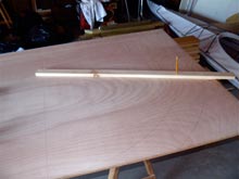 |
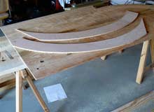
The first step was to mark and cut out the two plywood stem halves. I made a rudimentary compass out of a stick with a hole in one end for a nail and two holes in the other end four inches apart and big enough to accommodate a pencil.
click images for larger views |
 |
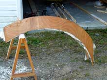
After some comical battles with my memory of high-school geometry, I was able to trace curved shapes that made full use of the 4-foot width of the half-inch plywood with flat “feet” for attachment to the keelson. |
 |
Matching holes were drilled along the front edges of the stem halves, and they were wired together with copper electrical wire, twisted enough to secure it, but not overly tight. I save all the little pieces left over from wiring projects for uses like this. It’s kind of a pain to have to strip it, but it sure beats buying new copper wire at today’s prices. |
 |
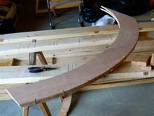
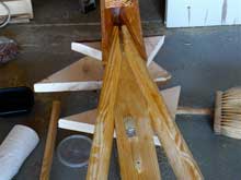
Then I cut some wedges out of yellow pine, taking the angle from the Lark plan, to insert between the halves and make the stem take its proper shape. This photo also shows just how nice the AC plywood is. |
 |
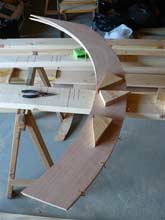
Next the halves were pulled apart and the wedges buttered with Titebond III and driven into place. If you’ve ever tried to hang a multi-hinged door that’s warped enough so that the hinges don’t line up right, you’ll know that the plywood doesn’t want to be forced into this shape. I’m convinced that the “torturing” of the plywood this way actually makes the resulting structure stronger, but it makes for some interesting assembly quirks--like one little wooden wedge being spit out and flung across the room. while you’re trying to get the next one into place. Wear safety glasses and be prepared to duck, and drill some holes in the plywood where the wedges are going to go, for temporary screws or nails to hold them in place while the glue dries. You can just barely see the nails in this photo. |
 |
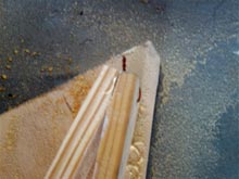
The inside of the wired joint was then fastened with glass tape embedded in epoxy. I also filled the joint with a crude fillet of thickened epoxy (it’s hard to reach all the way in there), inspired by the epoxy pours that added so much strength to the bow and stern of my wife’s CLC kayak.when I was putting that boat together. Here you can see more clearly the temporary nails that hold the wedges in place. Note also the very few small voids in the edges of the plywood. Those were filled after the photo was taken. |
 |
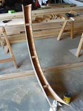
The next day I snipped off the copper wire on the outside, sanded the stubs until the surface was smooth, and glassed the whole stem. The resulting structure seemed very strong and was satisfyingly light. But since the stitch-and-glue stem has no rabbets to receive the ends of the longitudinals, I had to come up with a different way to attach gunwales and chine logs. |
In what I truly believe to be a moment of inspiration it occurred to me that they could be epoxied inside the hollow stem, using bronze screws driven through the stem and into the longitudinals from outside This method assures a relatively large gluing area, and also allows space for the addition of a plywood lamination on the outside of the longitudinals after they are bent into shape but before planking. The extra plywood serves to strengthen both the longitudinal itself and its curved shape, and also to provide a fair surface between stem and longitudinal for the planking.
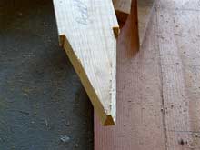 |
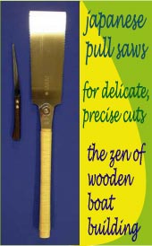
Now I was almost ready for the fun part, as I got to see how all the components fit together to make a boat shape. But first I had to notch the keelson to fit the stem, and the chine logs to fit into the keelson/stem joint. Here’s the keelson notch, made with a jigsaw and a small battery-powered circular trim saw, with a little help from a Japanese pullsaw. |
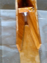 |
Fitted, it looks like this. Sorry this photo didn’t come out as clear as it should have. |
 |
I fiddled with the chine log notches using the same tools as for the keelson. I could have gotten a tighter fit between them by extending the notches just a little bit more, but told myself at the end of a hot day that there was already a lot of gluing surface here, that I really needed a beer and a swim more than the joint needed more fiddling, and that the gap would be a nice place for some strengthening via thickened epoxy. This is why the Lake Skiff will probably never make it into WoodenBoat. |
 |
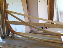
The gunwales presented a different challenge. The complex curve of the sheer makes them misbehave. The photo shows what they want to do when you spring them into place. Even I know that this isn’t good enough. |
 |
After a few false starts I decided to take a rasp to the meeting edges of the gunwales, wire the suckers together and then fit them into place. Worked like a charm. |
 |
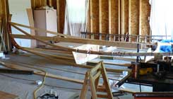
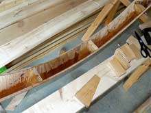
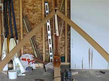
The boat began to take shape as the longitudinals were bent around the mold and fastened to the transom. |
|
The natural tendency of all this sprung wood is to flatten out the rocker. The 2 x 6 strapped into place and the blocks under the stem prevent that from happening, until the planking and the vertical component of the keelson (which is actually a t-section) are installed. You’ll notice that the mold is fastened to the keelson with an angle bracket, and that that it leans forward a bit. I found that tilting the mold was a good way to make minor adjustments to the sheer until it looked the way I wanted it to. The clamps along the gunwale are where the first section of plywood outer lamination has been added. In the next installment some planking goes on and the hull begins to look like a hull. |
*****
On to Part 5
|