My on-and-off girlfriend recently stipulated that she needed
her boat again. The boat she referred to was an 8’rowing/sailing
boat I built for her two young daughters 30 years ago. In those
days she herself considered it logical to be on board as ballast.
So her offspring soon became accustomed to crawling over her
and the little spare room left after she had spread out her
gorgeous body on most of the bottom area. They did not bother
and actually considered it practical as this way they could
effectively keep the many admirers she attracted and still attracts
at bay. Times went by and along came two grandchildren, now
three years old, thus reminding her of her maritime responsibilities.
But the old boat has done quite some circulation in the large
family, teaching many children the principles of rowing and
sailing on its way. However, it was not always properly protected
but abused. The latest reports tell that its working days are
over as the traditional ply construction is falling apart.
 |
My present ’epoxy
vacation’ (a side-effect in the process of building
a 40’ sailing vessel) met with a growing feeling
of guilt towards the needs of my girlfriend. So, another
little boat had to be built. |
My present ’epoxy vacation’ (a side-effect in the
process of building a 40’ sailing vessel) met with a growing
feeling of guilt towards the needs of my girlfriend. So, another
little boat had to be built, this time in the open air outside
my shed for maximum ventilation. As an amateur I have always
liked to genuinely design boats, but now I took a less formal
approach, even the other way around, not unfamiliar to Duckworks
readers. Having in mind a stitch and glue project I bought some
sheets of stiff paper and cut and glued for a couple of hours
until I had a satisfactory model that more or less did express
the very shape I had in mind. The only restriction I had was
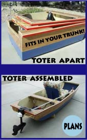
the fact that the backdoor of my car accepts a maximum width
of 2’ 7 ½”. So that was to be the –still
acceptable- width of the bottom panel. I needed as a start two
4’x 8’sheets of 3.6 mm. interior Meranti ply, which
at least in my experience has proved to be quite resistant to
whatever the weather may throw at it. One sheet was cut in length
at a width of 2’ 7 1/2:” to provide for the bottom
and transom panels. The other in three panels respectively 17”,
17”and 14”wide to provide for the sides. Some scarfing
was necessary to get the proper length. The bottom panel needed
an 11”extension at the bow. The side panels needed all
an extension of 22”, gained from the 14”wide leftover
(See sheet I and II and their cuts).
| I needed as a start two 4’x 8’sheets
of 3.6 mm. interior Meranti ply, which at least in my experience
has proved to be quite resistant to whatever the weather
may throw at it. |
|
This story is primarily about how to assemble a little hull.
Measurements and stitching start at the bottom of the transom
and move forward. Please note that on sheet I the station 0
is at the left side of the sheet (bottom sheet), while station
0 on sheet II (side panel sheet) starts at 3 ¾”
from the left side. The side panels consist of a lower and a
upper strake, and only need to be curved at the intersection
of the lower and higher panels. Both twist from stem to stern,
especially the lower one. Put on top of each other they are
stitched loosely together along their curved edges, starting
at the after end. After carefully unwrapping them into a proper
angle and tightening the stitches as needed, it was pretty straightforward
to stitch them to the bottom panel and the transom panel. The
bottom chines as well as the sheer conveniently accept the straight
edges of the ply, although after adding the gunwales a minor
trimming of less than ½”of the ply sheer near the
stem took place.
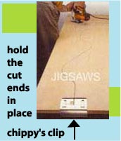
Stitching was done using nylon fishing thread, although cable
ties might have done the job also or even better. Chosen stitch
intervals were mostly at 8, but 3 mm. holes 4”apart were
drilled to put them closer if necessary. Bringing the forward
ends together and stitching them to the stem brought about the
rough shape of the hull. The stem was in my case a piece of
hard blue foam, cut to shape. Forming the transom needs some
explanation though. The back of the boat actually consists of
two flat parts interconnected at the upper chine. The straight
and sharp bend of the chine results from cutting halfway (some
1/16”) deep into the ply with a precisely set circular
saw. Then carefully bend the ply along some straight edge. The
remaining ‘gutter’ on the inside is filleted afterwards.
(I also use this method whenever I have to bend ply to a nice
flowing short curve, in which case making multiple cuts alongside
each other; sometimes reinforced with glass on the inside of
the bend.)
 |
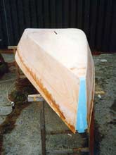
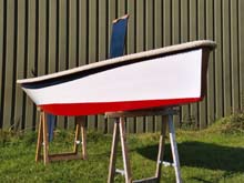
After two days of preparatory
work, cutting the panels and fiddling with them, the boat
had derived its rough shape. |
After two days of preparatory work, cutting the panels and
fiddling with them, the boat had derived its rough shape. A
temporarily fitted cross brace produced (a trifle more than)
the proper breadth (4’) and a desired rocker bottom of
4”resulted. It was expelled with afterwards, but the remaining
studs were used to attach cleats. The next day the epoxy fillets
were applied to stiffen the hull on the inside. After curing
(pretty fast using the heat from an electrical radiator) the
hull was turned over. The outside of the boat got the usual
planing, sanding and filleting treatment, and the lower outside
of the boat was entirely wrapped in one glass sheet, cut to
about three inches up on the sides. For reasons of preserving
light weight (empty hull weight to be less than 70 lbs) the
glassing was kept restricted to this most critical and abused
area.
| The gunwale took some extra concern. The
idea was to apply a fender of thick rope all around. It
asked for a recess in which the four strand 1 3/8”diameter
rope would largely be encapsulated. |
|
The gunwale took some extra concern. The idea was to apply
a fender of thick rope all around. It asked for a recess in
which the four strand 1 3/8”diameter rope would largely
be encapsulated. I started with the application of pine strips
that had three sides one of which was hollow. A pair of the
right dimensions and opposite of each other would produce a
neat and tight cove. However, I noticed that when bending, forces
caused uncontrollable twisting of the strips and prevented a
direct and easy application. For that reason I prefabricated
gunwales consisting of three components. A flat piece of wood,
1 ½”wide would be situated against the outside
of the ply sheer, and glued to that strip are the upper and
lower hollow strips. But then it turned out that the outer hollow
elements in this rubrail needed to be of excellent quality.
Although the portside went on flawlessly, minor imperfections
of grain run out twice caused premature breakage of the starboard
side, when (almost) put in place. Although not very costly,
it took an extra day to get it right. In general, I now would
hesitate to recommend to beginners the application of gunwales
this way. Redoing this gunwale thing I might try and use a less
elegant approach, applying laminations of rectangular hardwood
strips of some ¾”x ½”, fitting two
laminates 1 ½”apart and trimming them to accept
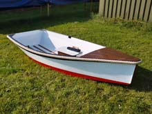
the rope. Whatever the method, the result is worth the trouble,
if only for the ‘salty looks’ of the boat as passers-by
commented.
 |
Redoing this gunwale thing
I might try and use a less elegant approach. Whatever
the method, the result is worth the trouble, if only for
the ‘salty looks’ of the boat as passers-by
commented. |
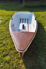
In order to adequately strengthen the bottom panel, four floor
battens of hardwood stringers ½”x 1 ½”have
been applied. Leftovers of Okoume marine ply were used for the
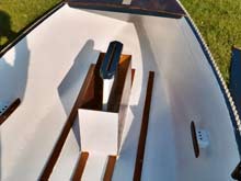
rudder (3/4”) and daggerboard (5/8”). The daggerboard
trunk case is of the usual construction, making sure that its
sides run to the bottom and that it has a 4”wide base
to accept sideway forces. A 7-1/8”wide and one foot high
case was also built around the trunk case. It was firmly glued
to the bottom panel, the outside of the inner floor battens
and the front end of the trunk. It helps to reinforce the trunk
case, but is primarily intended for storage of small items while
its top cover offers access to the case, at the same time providing
the rowing seat for Her Majesty (rowing is especially envisaged
in the city canals during the many festivities). A small foredeck
of leftover 5 mm. Mahogany marine ply has some structural function
and a hole in it accepts the mast, which is stepped further
into a rectangular notch glued to the bottom panel. No benches.
They would interfere with the aforesaid dynamic system of ballasting
the boat while sailing. No built-in buoyancy either, as I doubt
whether a boat of this size could be righted in the water anyway.
It will not sink and the children always wear lifejackets and
should stay with it until help arrives.
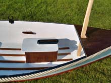
| A 7-1/8”wide and one foot high case
was built around the trunk case. It was firmly glued to
the bottom panel, the outside of the inner floor battens
and the front end of the trunk... |
|
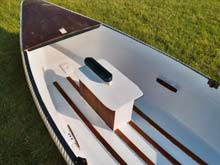 |
... It helps to reinforce
the trunk case, but is primarily intended for storage
of small items while its top cover offers access to the
case, at the same time providing the rowing seat for Her
Majesty. |
The gunwale fender rope is supposed to be replaceable and hence
was attached with thin stainless steel wire through small holes.
For cosmetic reasons and protection the wire was worked into
the contlines, the spiral spaces between the strands. To this
end the rope was put in place and the holes were drilled in
the upper and lower ‘cheeks’ of the gunwale cove,
at a total of 15 positions, which were some two feet interspaced.
The mast is unstayed with a lugger sail. The boom has a claw
around the mast. Setting sail is straightforward and takes hardly
any time. I like the final result which comes close to the concept
I had in mind. The panel specifics are in the table and diagram.
For non-commercial purposes the diagrams, data and photographs
are free for use. Given the concise information, building may
require some experience, especially working out a multi chine
construction with warped and initially flabby panels on two
saw horses. Furthermore, one should be familiar with the different
uses of epoxy. All in all, the project took exactly three weeks,
including shopping and making the spars oars and sail. The earlier
dink took only two weeks, so I might have slowed down a bit.
But, while the former project normally could go on, this time
I also had to pause for the epoxy to cure or for inclement weather
(the former boat was built inside and the glued resorcinol connections
were doubled by screws.).
| Costs were restricted as my main project
(40-footer) produced scrap material, epoxy stuff and paint.
Even the Oregon pine spars and oars were leftovers from
mast building. |
|
Costs were restricted as my main project (40-footer) produced
scrap material, epoxy stuff and paint. Even the Oregon pine
spars and oars were leftovers from mast building. Two ply sheets
did cost $30, 20’ of polypropylene gunwale fender rope
$50, sail cloth $55, wooden strips $40, hardware may be $90,
totalling some $265.
Diagrams
(click images for larger, printable versions)
List of relevant measurements, all
in inches
Measurements are usually one foot apart; starting at the bottom/transom
intersection. (station 0). The bottom and side panels continue
beyond the limits of the 4”x 8”sheets, so some scarfing
will be needed to arrive at the proper lengths. I like to scarf
already shaped ’end panels’, instead of scarfing
large panels beforehand. I clamp the side to be worked on along
the edge of a bench, marking the width of the scarf and using
a power plane. Pretty fast to me.
| Station |
Bottom |
Lower side |
Upper side |
Stern |
|
* |
** |
0 |
21-¾ |
11-¼ |
3-5/8 |
1 |
26 |
11-½ |
4-3/8 |
2 |
29-½ |
11-¼ |
4-3/4 |
3 |
31-3/8 |
12 |
4-7/8 |
4 |
30-½ |
13-3/8 |
4-3/4 |
5 |
27 |
13-¾ |
4-1/8 |
6 |
21 |
13-3/8 |
3-1/8 |
7 |
14-1/8 |
13-1/8 |
2-5/8 |
8 |
7 |
13-¾ |
2-1/8 |
9 |
1-½ |
13-¼ |
2 |
Stem |
|
*** |
**** |