Part 3 of 4 - Construction
Part One - Part Two - Part Three - Part Four
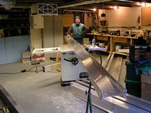
Now it’s time to test out the theory. The previous two articles were just talk, this is where I get a few more scars on the hands. The first job is to cut up the I beams into the correct size pieces. At nearly 20 foot long they are too long and heavy to cross cut on the table saw, so I have to raise them with a few wooden blocks to get my chop saw underneath. There was a cheap blade on the saw which ended up like a toothless old hag after four cuts, it did manage to pay me back though by flicking a hot piece of aluminium into the corner of my lips, which took the grin away for a few hours. I would definitely recommend an aluminium cutting blade rather than a wood rip blade, or if you do use a wood blade, make it a medium cross cut blade. Lubricate it every half dozen cuts with a squirt of WD40 on each side, otherwise you will find the teeth get clogged. Aluminium chips aren’t like sawdust so it goes without saying that goggles and ear protectors are required and don’t think that you can get away without using the goggles because you wear glasses, you can’t - trust me on this one.
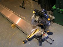 |
A chop saw is the easiest way to cut the 20 foot beams to size. |
Once the beams had been cut down to size the cross pieces at 6’ 3” could fit onto the table saw to cut the tenons in the top and bottom rails at each end, to allow the rib to fit into the trailer side rails. After the first cross cuts, I slid the ends into the saw blade to cut the bits of top and bottom rail off. To avoid cutting too deep, because the circular blade was angled, even on full height, I finished the job off with a hack saw. With the rib exposed I shaped it with hacksaw and file on the four cross rails and four suspension stubs.
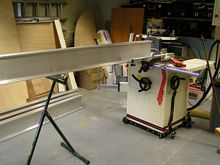 |
Cutting the tenons. It can be a lot of hard work making something like this if you use hand tools, so I try and use power tool wherever possible. |
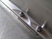
Next job was to cut the 8” x ¼” bar into smaller pieces to reinforce each joint on top and bottom. The only exception is the bottom of the four joints where the suspension will fit. The tops of the suspension units will be painted with 3 coats of epoxy to protect them and isolate them from the aluminium frame (as will the bottom of the coupling). With the reinforcing bar cut to size the bolt holes need to be drilled to take the shoulder washers. After careful measurement I decided to place the bolt centres at 16mm from the edge of the beams and 30mm from the ends. On each plate there will be 4 bolts into each beam, so either 8 or 12 holes to be drilled on each plate, depending on its profile and where it fits. There could be a number of successful ways of doing this, as the way used worked so well I can recommend it. Firstly measure and locate the hole centres with a centre punch. Drill small taping holes on one plate of each shape, then widen these holes to 3.5mm. Now take the other plates of the same shape, one by one, clamp to the plate with holes and drill using the first plate as a template. After each of the first 3 holes, put a small clout nail of the same diameter as the holes to prevent the plates moving. When all the plates have 3.5mm holes expand them to 8.5mm and then 12mm which was the outside diameter of the shoulder washers. On this last drilling, first drilled ¾ way through the holes from one side then turn over and drill through to prevent breakout. This gives holes in identical places to the extent that the tight fit shoulder washers could be pushed through two plates together (the washers were over length and will need to be cut down).
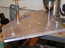 |
Drilling plates, use the first one as a template to locate all the soles in the same places. |
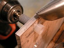 |
Cutting down shoulder washers. I used a carborundum stone in the drill to provide some friction to rotate the washer in a plate of the correct thickness. A sharp Stanley knife then makes a clean cut to the excess washer length.
Notes:
- For extra length use penny washers to pack out the shoulder washer.
- Make sure you get the drill rotation in the right direction.
|
It just goes to show that you can’t think of everything, or at least I can’t. After having cut and drilled the plates over the suspension arms to size I decided that the stubs should be narrower for the suspension plate hole centres to be 16mm from the edge, this meant that the top plate holes were too wide, but I left them like that rather than re-drill.
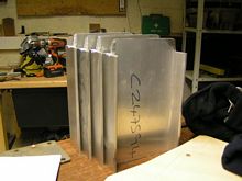 |
Suspension stubs cut to size and shaped ready to be fitted. |
 |
Suspension stubs fitted with fixing plates bolted on top. |
Although the basic design of the trailer has already been done, there are still a few parts where I don’t quite know how to finish the details. One of these is the bunks – do I have longitudinal planks shaped to size, or cross members on the four cross rails to support planking? How do I keep the keel on the centre bunk – some sort of shoe or guide side rails will be a good idea maybe? These details will have to wait until the trailer is built, I am sure they will slip into place at the appropriate time.
I just had a chat with my accountant who used to have an aluminium canal boat which he towed on a trailer. The boat was about 3 tons and ballasted with water, which towed very nicely behind his Landrover Discovery (the same as I drive). On one occasion he pulled the boat up the ramp to find the extra load of ballast water had bottomed the suspension, and as the mudguard brackets and bolts were over the wheel, the bolts had gouged two furrows in his front tyres. I don’t think this will happen to me as I have no water ballast, but it may be worth allowing a little extra space and not placing bolts over the centre of the tyres.
IMPORTANT NOTE:
As mentioned in the previous article I am using stainless steel bolts to fasten the trailer together. Stainless nuts and bolts are subject to galling, which sticks and even welds bits of the thread surfaces together when tightened due to a mixture of friction and adhesion, even up to the point where they cannot be undone. Parts of the frame need to be fastened temporarily, using BPZ nuts, until I make the final assembly - dissimilar metals are not subject to galling.
Now for the first problem! When the aluminium beams were bought, I envisaged they would be like steel RSJs with a flat inside cross section on top and bottom. However when they arrived the top and bottom inside edges were chamfered and would need to be trimmed, to allow the washers to sit flat. This could turn out to be a large job, so I considered the options:
- Pack with a wedge shaped washer. Good idea but costly and the wedge would have to be aluminium, also the bolts would need to be changed for longer ones.
- Cut with an angle grinder. Good idea but would a freehand cut be absolutely parallel to the outside of the beam to allow the bolts to exert all-round pressure on the washers.
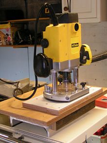
- Make a router jig and use a long round tip blade. Again, good idea but not accurate enough. It would have been fine if I had a milling machine and metal cutting bits. £25 wasted on a router bit!
- USE THE TABLE SAW. After wasting a morning struggling, my friend David, who was helping me for a couple of days, came up with this idea.
 |
The failed router jig. It was a good idea but cutting hard aluminium accurately this way is like trying to drill a hole in a sloping piece of wood or metal. The drill will keep sliding off if it is not at 90 degrees. |
For the smaller beams that would fit easily on the saw I placed them on their sides against the guide and slid the ends into the saw blade (set to the right height) - this trimmed the aluminium to perfection. For the side rails, which were long and heavy, this method would not work. The new method was to place the beam in the right place with the saw blade on the lowest setting, then slowly wind up the blade to the correct height, on my saw this was 14 turns – again a perfect cut.
 |
Side rail on saw for cutting. This proved to be an easy and accurate method. |
 |
Finished article, note the size and shape of the cuts. This is only a temporary fit of the suspension template, the shoulder washers have not been included yet. |
Not having a level building site makes the job a bit harder, the garage floor is not only sloping 4” from front to back but is also uneven so all the pieces of aluminium must be propped and levelled with wedges. The garage is about 19’ long, so I can just fit the body of the trailer without the draw bar with about 2” to spare, in fact the side rails needed to be adjusted by 3” to make them fit with the A frame fixing plates attached. After a few trial attempts I decided the trailer has to be constructed in a certain order to make it possible.
- Assemble the body upside down ensuring all the rails are level.
- Hold the side rails to the cross rails with Spanish Windlasses. This method will allow me to square up the frame with the help of a rubber mallet. NOTE do not tighten it too much as this will bend the side rails, which are not designed to take side loading.
- Drill and bolt the corner plates and dummy suspension plates made from ply to hold the bottom of the unit together.
- Turn the body over and level it up again, in my case this consisted of undoing it all and turning each beam over then reassembling it.
- Drill and fix the top plates.
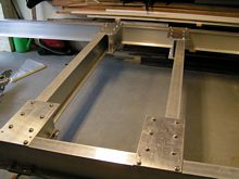
I now have a complete rectangular frame bolted with temporary BPZ nuts
- Remove the dummy suspension plates and bolt on the real ones. For this the frame needs to be raised a bit higher.
- Shape the A frame and locate the T piece in the centre – this is for extra strength and to fasten the winch post to
- Drill the coupling (tow hitch) mounting holes and bolt it on
This in essence is the sequence to complete the structure, but it will not fit in the garage, and it is still too cold and wet to consistently work outside so I will take off the A frame and complete the trailer body, adding it again at the last stage after wiring up the lights and brakes (to be covered in the next article on finishing off).
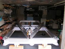 |
Progress so far. The A frame is built and resting on the body of the trailer until it is time to tow it into the garden. I intend to fit the wheel, lights and part wiring before moving it and inserting the brake rod. This will be the content of the concluding article. |
After a bit of further research on the net I decided to modify the design and just use Locktite 2701 which is specially formulated for use with chrome alloys (a component of stainless steel), it has a quoted breakaway strength of 38Nm (28 foot pounds) which seem very little, so I phoned the technical helpline for advice and was told. “The quoted breakaway is a specific test where the nut is loose on the thread, if you torque the nut down it will not be possible to undo it, unless it is heated to about 250° C”. Not what the specification suggested. Don’t you just love the technical helplines, they provide the critical information that is missing from the specification.
Click HERE for a list of articles by Mike Machnicki
|