The OAHE 1530
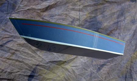
This hull design is some what the same as the Reservoir 1525, but it's a bit wider at the beam, and the transom is quite a bit wider than on the Rez. Dr. Doug, the “launch order requester” for the Rez; was happy with the hull, but kept asking about how to make the sides a little higher. After several emails about changing what the “designer” had in mind, the designer finally changed his mind. I must be a push over, or just like a challenge, so it was back to the drawing boards (laser mouse) for this “bigger/taller” hull.
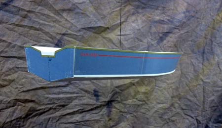
Early on, the lofted up, taller sided versions of the Rez looked wrong, and I told Dr. Doug as the design progressed, butt ugly. So it was put aside for a while, and I went back to working on my “John Duc” hull. After a trip to the Big Seattle Boat Show, sung to the tune of “boat show, boat show, the big Seattle boat show”. You get tired of listening to radio in January around here; I took the bus into town with my camera. I wanted to see what the “big boys” did, and whether those ideas could be turned into stitch and glue construction. I found that if you “liked big transoms”, you kept the bow rise to zero at the rails.
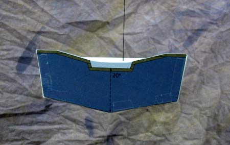
Now that I knew what I had to do to get this higher sided hull to look good, it was back to the computer to redraw the lines. First off, I widened the hull overall, and then widened the transom to almost the same width as the beam. I increased the height of the transom as well, and the hull will require long shaft outboard motors, but there is still a cut down in the center to mount even a LS. Once that was completed, it was time to work on the top line at the forward end of the side panels. After numerous cardboard models, the light finally clicked on in my brain that I was approaching the problem from the wrong side of the line. I sat one of the models level on my kitchen counter and used a block of wood to hold a pencil. I then slid the block/pencil along the counter top, and drew a line on the model hull. Once I “deconstructed” the model, I could see what I had to do. Several models later, (it's not as simple as you think) and minute changes to the arc of the curve (and the base angle of the beizer curves handle point) I got what I wanted. If I had an extra $10k and twenty years to learn Auto Cad’s Inventor, I probably could have had a hull the first time out, and all the interior parts, their actual measurements, and 3D PDF construction drawings. It's that good!
Most of the other construction ideas about plywood sizes, and the final weight of the hull for the OAHE 1530 can be read in the cover letter for the Reservoir 1525, which is already posted here in my plans section if you want to read more on this hull. They are close enough in size/shape to be in the ball park, but his hull will probably use butt joints instead of scarfs. I will know when I start on the construction drawings.
I will not be doing a prototype of this hull, but I will have several drawings of possible interiors that can be fitted to the hull. You will probably have your own idea of the boat that you want, so I will caution you to keep the “hulls balance” in mind as you build. Once you have the main panels of the hull put together with epoxy and tape, you should find the “balance point” of the hull at that point. When you start adding the panels for your hull, you will want to counter any weight in one end, with a corresponding counter balance of wood in the other end.
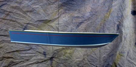
Enjoy putting this PDF model together and making “your interior” for it. Just remember to keep the hull balanced. Put your model on a round pencil and find the balance point, and mark that location. As you model your interior, make sure the model still balances around that initial point. Have fun. You can also layout the PDF panels on thin model aircraft plywood, and make a wooden version of your hull. Enjoy.
Thanks Again
Warren Messer
Red Barn Boats

click the image above for a free PDF
file to print and build a model from
|