|
In this, the first of a four-part
series of articles on the design and construction of the
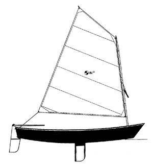
sharpie skiff, Nemah, we will look at the "whys"
that affect boat designs in general, and then go through
the actual process of developing lines, offsets, and panel
shapes for a 15-foot sailing sharpie.
 The
first consideration in the design process is purpose: What
are the intended uses of the boat? We have to ask this question
in the plural, as boats are often expected to be suitable
for a variety of tasks. Implicit in this question is a host
of other questions, such as intended load, anticipated local
conditions, speed requirements, physical abilities of the
users, intended method of transportation, and storage environment.
In this regard, the designer usually finds himself faced
with the unpleasant task of explaining to a would-be client
that what he wishes to accomplish is either physically impossible
or unaffordable! The
first consideration in the design process is purpose: What
are the intended uses of the boat? We have to ask this question
in the plural, as boats are often expected to be suitable
for a variety of tasks. Implicit in this question is a host
of other questions, such as intended load, anticipated local
conditions, speed requirements, physical abilities of the
users, intended method of transportation, and storage environment.
In this regard, the designer usually finds himself faced
with the unpleasant task of explaining to a would-be client
that what he wishes to accomplish is either physically impossible
or unaffordable!
Once we are able to state
our intended uses in order of importance, we can begin to
assemble a list of hull shapes that are well suited to our
primary purpose, and yet will lend themselves to the secondary
uses listed as well. In practice, the range of shapes seriously
considered by individual boaters will be limited by the
notion of what to them constitutes a "boat", both
structurally and asthetically, as well as a list of details
they feel strongly about, one way or the other. These would
include materials (wood, aluminum, etc.), and may include
an almost endless list of other considerations; such as
bottom shape, outboard location, leeboard/centerboard, rig
type, and so forth.
In choosing the hull shape
and rig for Nemah, my major considerations were: 1. Sailing
ability. 2. Ease under oars. 3.The ability to accept a small
outboard motor. My interest in hard-chine hulls in general
and skiffs in particular could be regarded as my "notion
of what constitutes a boat," in
light of the intended purposes of this design.
Sailing hulls require at
least moderate amounts of bottom width to keep on their
feet, while ease under oars requires that bottom width be
held to a minimum. By fitting the hull with a fairly wide
transom that is out of the water when under oars, we can
provide increased waterline length and lee displacement
under sail, while still ensuring a good wet shape when rowed.
By fitting the transom at between 12 and 15 degrees, we
can establish a proper thrust angle for an outboard. (The
wide transom also allows a loose-footed sail to be properly
trimmed close-hauled, which we will go into in more detail
in the second part of this series.) My desire to maintain
rowing ability affects my choice of sailing rigs, since
if the heeling effect of the rig can be minimized, then
the bottom width need only be moderately wider than would
be optimum for ease under oars. With a sprit rig, the heeling
effect will be significantly less than a jib-headed rig
of equal area, with the added convenience of spars that
can fit inside the hull.
After deciding upon a general
hull configuration (in this case a sharpie skiff), we need
to consider intended load, because it plays a major roll
in the determination of the actual size of the boat. I arrived
at the overall length of Nemah by determining how much boat
I could build using side panels cut from a 16-foot sheet
of plywood, given a predetermined hull width of about 4'4".
Nemah's load capacity of 2 to 3 adults or 2 adults and a
couple of kids is based on beam and hull depth as well as
length. (A 6-inch reduction in beam would reduce this hull's
safe capacity by at least one-third; in addition, her handling
with the same sail area would go from "lively"
to "treacherous,")
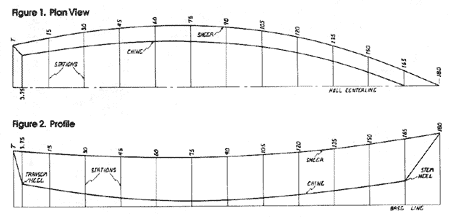
 figures 1&2 (click to enlarge)
 |
Lines
After I've cleared the mail off my drawing board, washed
my triangles, taped down a sheet of vellum, and made myself
a cup of tea, I've nothing left to do except put pen to
paper.
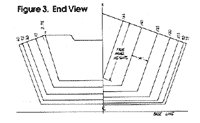
 figure 3 (click to enlarge)
 |
For a design such as Nemah, l do what
is known as a "cylindrical development", which
will yield a hull whose panels are sections of a cylinder.
This type of hull is often called "straight sided",
but the term is confusing, because these hulls can have
flare, tumblehome, deadrise, and so forth, as well as boldly
developed curves. The only thing "straight" about
straight sided designs is that their section lines are parallel
to one another when viewed end-on (see Figure 3).
I generally develop my designs from three
lines in two views: the sheer line in plan view (a top view
of the hull), the sheer line in profile (the hull viewed
from the side), and the chine line in profile. Because I
derive all additional lines mathmatically, I normally do
not draw an "end" view of the hull. Because an
end view is needed to do this type of development without
a calculator, I have included one in this article.
The first line drawn is the sheer line
in plan view (see Figure 1). In Nemah's hull, the
widest point is just aft of mid-length, and has a full-
scale half-breadth of 25.8". At the transom, the half-breadth
is 17.64". (Once down on paper, this line is definitive.
Stations are layed out and half-breadths are taken off with
an engineer's 1/50" scale to the nearest
1/100th, then upscaled by calculator and recorded on the
table of offsets to an accuracy of two decimal places.)
Usually the sheer line in profile is
layed down by "eye" and its heights upscaled and
recorded. On Nemah, I opted to "straight plank"
the sheer; that is, make the top of the side panel dead
straight, and so derive its curve in profile from hull breadth
and side flare (see Figure 2), This was a common
practice among old-time dory builders and usually results
in a nice sheer line. Station heights are easily derived
either by calculator or from the end view drawing once you
establish the angle of side flare.
The chine line in profile is the most
difficult line to draw. It has to account for hull depth,
bottom width, freeboard, draft, waterline length, and ultimately,
displacement! Here is where you stare at the drawings in
American
Small Sailing Craft until the lines are
burned into your brain.
In drawing Nemah, I first established
her hull depth amidships, and then drew a preliminary load
wateriine in pencil. Knowing that I wanted the heel of both
the transom and the stem to stand clear of the water, I
was then able to lay down the chine line by "eye,"
but not without a point of reference.
Because Nemah
is to be of plywood composite (sewn-
seam) construction, and no frames or building jig
is to
be used, the exact shape of each plywood component
must be determined prior to assembly. |
The exact point of the chine line's aft
termination is easily established by drawing the transom
in profile at whatever angle one chooses, but the stem heel
is a bit more difficult to locate. The most accurate way
is to pencil in several additional stations near the stem
in plan view, and then determine the height at which the
side panel will touch the centerline for each station. By
plotting several of these points on your profile drawing,
you can establish the line of the stem. The point at which
the stem line crosses the chine line is the stem heel. I
draw in an additional station at this location and record
it on the table of offsets.

Because Nemah is to be of
plywood composite (sewn-seam) construction, and no frames
or building jig is to be used, the exact shape of each plywood
component must be determined prior to assembly.
To derive panel widths mechanically,
take off the sheer and chine point locations from the end
view drawing, by measuring down from a line drawn perpendicular
to the side angle of the boat. (On Nemah, these measurements
can be taken directly from the end view sheer line, but
this is usually not the case.) Bottom panel widths are taken
from the table of offsets and layed out from the panel centerline.
Expanded stations must be
determined for each panel separately, as their curves are
not equal. True station distances for the bottom panel can
be lifted off the profile drawing by simply measuring from
station point to station point along the chine line. To
determine the amount of expansion for each station of the
side panel, we have to resort to a little simple trigonometry:
If we take the distance between each station as measured
perpendicular to the station lines in the end view (distance
"A" in Figure 3) and apply the following formula
to it, we will arrive at a fairly accurate
figure.
The
expanded station distance is equal to the square root
of the sum of the end view station distance (A) squared
and the profile station distance squared.
The widths of the transom
at sheer and chine can be determined from the table of offsets,
while its true height can be taken directly from the profile
drawing.
In Part II of this series,
we will consider construction materials, interior layout,
and the development of a sailing rig for Nemah.

Visit Tracy's website:
https://www.tracyobrien.com/
|

