| For me, shaky hands and a powerful angle grinder were not the right formula for a perfectly faired centerboard foil. I happen to be one of those guys with limited handyman skills and was really nervous about shaping NACA foils for my Pathfinder from the substantial block of wood that I glued up.
I came up with a fairly quick “jig” solution – the concept was to turn my router into a “variable height” planer. As with most parts of this boat project – describing the process is harder than actually doing it.
How it works...
The idea works kind of like an inkjet printer where the cutting “head” slides back and forth over the block of wood, except it changes its depth appropriately, by following the jig profiles. In short, I set my router at a fixed depth and slide it across vertical pieces of plywood, cut in the shape of my foil, thereby removing only the “right” amount of wood. The plywood jig is built wide and tall enough so that it fits over the foil “block”, so the block of wood slides underneath.
 |
I came up with a fairly quick “jig” solution – the concept was to turn my router into a “variable height” planer. |
Since the router blade will be perpendicular to the surface of the wood block/foil, all we need to do is to cut out a jig shape that will maintain the router at a 90 deg angle to the foil shape. If we know the router depth and the slope of the foil at a given point, we can plot a series of points which form our jig shape.
Making the Jig - a bit of math....
Newton would have used calculus to “derive” the slope of the foil at any given point – I used a simple spreadsheet with the calculated NACA 0013 values (Pathfinder plans call for a 60mm "thick" foil over a "chord" width of 425mm...so 60 divided by 425 is 14...I rounded down a bit to 13 to allow for some fiberglass layers).
So for each “point” on the foil shape, using some basic trigonometry (which proved to be not so basic at times), we can calculate a point for the jig profile, which is equal to our router height (40mm in my case) at a 90 degree angle to the foil’s slope. If we calculate enough points, the result is a plotted line that is exactly 40mm above the foil shape.
If I’ve lost you at this point or the math bores you, you can simply use the spreadsheet attached here to feed in your own foil dimensions and NACA value….or if you’re building a pathfinder, there is a .pdf file for centerboard (print at 100% or no scaling).
 |
Click HERE or the image at left to download the spreadsheet |
 |
Click HERE or the image at left to download the PDF file |
No “lofting”
So, while the exercise in “math” was interesting, the really useful part is that you can simply print out the “chart”, then cut out the foil and jig shapes as real size patterns– no need to loft or bend a batten around a series of points. Using Microsoft Excel, I simply printed out the graph – measured its actual size on the printed page, and re-adjusted the height and width of the chart a couple times until the printed size matched the plan measurements. I had to tape together a couple pages, and I added some tape to the lines before I cut them out so that the paper would be a bit thicker for tracing around. Then I cut out the template and profile which I traced on to the plywood.
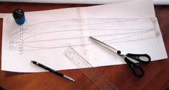 |
I had to tape together a couple pages, and I added some tape to the lines before I cut them out so that the paper would be a bit thicker for tracing around. |
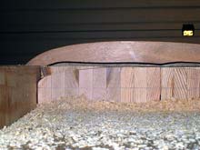
My jig “profiles” were made out of 12mm plywood which formed a stable enough platform. To hold the jig profiles upright and square I screwed them to longer pieces of scrap lumber that lined up with the centerboard “block” opening – these pieces then served as a bit of a guide as I moved the block through. The jig is screwed to the supporting piece of plywood, so the foil block slides through underneath, but I think as an alternative, you could slide the entire jig over a stationary block. I also found that the weight of the block generally held it in place, so even where the centerboard tapers somewhat, it did not move around. Lastly, I used a 1/2" straight cutting bit -- I think a wider bit would not have given good results for the nose, but I didn't do any experimenting.
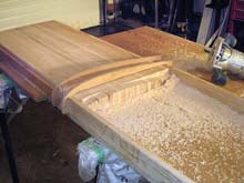 |
My jig “profiles” were made out of 12mm plywood which formed a stable enough platform. |
A couple of points that are important:
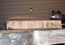
1. You need to start with a glued up block of wood that is square and lies sufficiently flat – my glued block was pretty decent and I only needed to take tear some excess epoxy off with a belt sander, and it was pretty much flat.
2. Don’t router off the end of the block (i.e. the centerboard tip) when you’re doing the first side– otherwise, when you turn the block over to do the other side of the foil ….it won’t be held square or symmetrical to your jig.
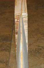
My goal was to find a really accurate way to get the right shape, and I wasn’t worried if this took more time, but I was surprised that this took less then a couple hours. I cut the jig shape from scrap pieces of plywood in a few minutes, and it took about an hour to run both sides of the block through the router jig. I spent another 30 minutes doing some minor fairing of the foil with 50 grit sandpaper. The part I’m not going to tell you is how long it took me to figure out the trigonometry bit – but for anyone who wants to try my approach, hopefully you can re-use my spreadsheet or .pdf files!
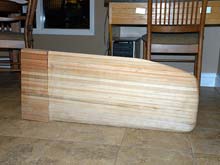 |
It took about an hour to run both sides of the block through the router jig. I spent another 30 minutes doing some minor fairing of the foil with 50 grit sandpaper. |
|