|
|
| Building
Annie - A Navigator 15ft Yawl - Pt 2 |
| By Robert Ditterich - Geelong,
Victoria - Australia
|
 |
| To
Part One
To
Part Two
To Part Three
A Pictorial Essay of a Navigator
Build
|
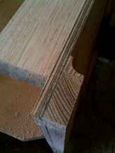
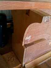
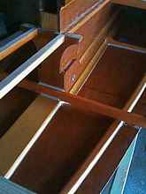
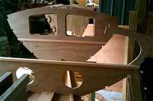
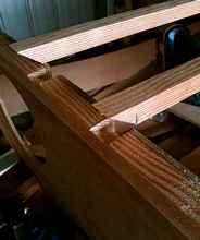
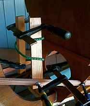
A close up of the top outer log attached to
the side and the molding. Note the back triangle of the molding
forms an epoxy fillet in that gap. |
|
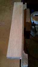
The top of the pic shows the bottom aft end
of one of the CB case sides, attached already to the end log,
the top outer side log, the bottom doublers, and in this case
I've also attached a molding strip traditionally called 'scotia'
in Australia. I've done this mainly for aesthetic reasons,
but it also adds better strength than an epoxy fillet (I think)
|
 |
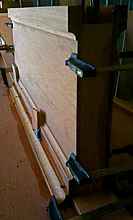
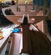
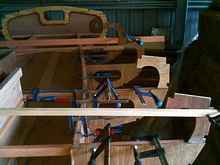
2 long f clamps pull the case firm against the
keelson, and are helpful to 'nuance' the verticality of the
unit. The other clamps are there because the interior of the
case has just had its third coat of epoxy ('glass fibre under
the first two coats) and the sides glued together. The whole
unit was then clamped and temp screwed then lowered into the
hole in the keelson. |
|
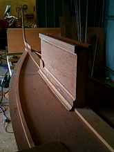
The bottom huge fillet called for in the plans
has been replaced here with a larger scotia molding, again
with the back triangle behind it forming an epoxy fillet of
normal size behind the wood. Because the floor is curved (concave)
this molding has been pulled downwards in the middle with
ply and temporary screws. The piece is backed by about 120ml
of epoxy plus 403 filler to make a very thick epoxy. |
|
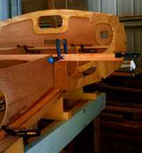
The case is still open from the top. The top
log will be attached to the case cap board, and will be screwed
in position but removable for maintenance/inspection. |
 |
Note that B3 here is facing the wrong way! The
20 x 20 strip along the plywood top will face forward. (Cobbled
together hurriedly for the photo.) |
 |
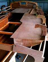
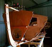
These bulkheads are just having their bases
cut to fit the stringer and keelson before being given their
first coat of epoxy. |
 |
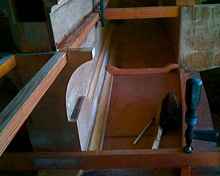
Bulkhead 8 has a beam that links the two sides
of the cockpit at the forward end of the rear seat, so the
space under and behind this bulkhead is a good and accessible
storage space. |
 |
B1 shown here has a 20 x 20 beam glued across
the face as shown in the plans. This is part of the support
structure for an anchor well that will be accessible from
on deck. It is supposed to drain from a limber hole at floor
height, out through the hull. Looking at other people's builds
many seem to choose a higher floor for the anchor locker.
Either the plans are wrong again, or there has been some serious
deviation going on...it does seem rather low... |
 |
Attaching these cockpit bulkheads needs to be
approached with some care because the cockpit seat front can
be distorted from the vertical- and needs to be checked at
each bulkhead- because the verticality of this panel will
impact upon the total width of the bulkheads, and therefore
the trueness of the stringer lines. |
|
For prospective builders - this piece has quite
a different shape from the one in the plans...nothing to do
with structure, though, just a shape I liked. |
 |
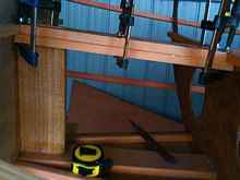
These stringers take seating ply on a slope
upwards to B3. I've cut angled housing joints in the 20mm
bulkhead top doubler to give a joint with good surface area
for minimum cost to the strength of the bulkhead. |
 |
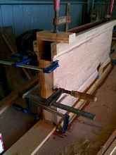
Wobbly, unsupported B3, two stringers with sweeping
curves, and a few other things being glued at the same time.
Keeping the bulkhead vertical while all this was happening
called for the old 'clamp-the-spirit-level-to-the-work-so-you-don't-have-to-let-go-of-something-to-check-it'
trick. |
 |
The 20 x 20 stringers that go along the CB case
swing up to B3 in a curve, or at least mine do because I fitted
them in one piece instead of having a join at B5. Surfaces
here are very grotty and in differing stages of prep for epoxy
coating. This is what I'd call an 'ugly shot'... |
|
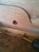
Managed to use a forstener bit to drill an oversized
hole through the ply, carefully stopping right on the inside
surface of the 3 epoxy layers. Left those in place to enable
me to fill the hole with thickened epoxy without having to
mask inside, or to have any unprotected wood remaining. |
|
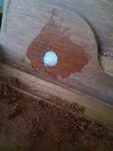
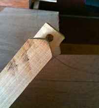
The hole is first smeared in unthickened epoxy
and allowed to penetrate the grain, then very thick goop was
pushed in, slightly over filling the hole. The next step will
be to drill a correct sized hole that will have a ring of
hard epoxy as a bearing surface. |
|
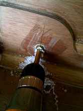
Here the epoxy filled CB pin hole is drilled
to fit the pin, leaving a bush of epoxy protecting the wood
and providing a good bearing surface. It is difficult to align
these two holes perfectly, and I'll have to introduce a bit
more epoxy while fitting the pin (smeared with a release agent)
. |
 |
...difficult to illustrate well, but here I'm
using a couple of sticks clamped to the stringers to lever
the stringers around to the vertical position so that they
lie flat on the stem. These sticks are drawn together with
shock cord and held with a clamp. I find this is preferable
to achieving the same thing by screwing the stringer at the
end, which is vulnerable to splitting. I did use a screw on
each side, into a pre-drilled hole, but only after checking
the verticality of the stem with a level. These 2 screws were
just to finesse the verticality, rather than holding the stringer
flat. |
 |
The first two pairs of stringers went in without
any dramas. The rebates already cut in the stem needed nuancing
a little so that the slot tilted downwards a bit - easily
achieved with handsaw and chisel. The angle on the leading
edge of the stringer was easily scribed by running a pencil
along the stem itself, marking a line parallel to the notch
a little in front of the stem. This extra length caused by
the thickness of the flat carpenter's pencil proved to be
about right for good length when the stringer was tucked into
its slot. |
|
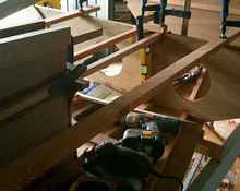
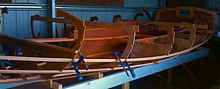
Before the stringers were fitted, the bottom
panel, cockpit seat fronts and some of the bulkheads were
given a coat of epoxy, and some of the corners gained a fillet.
It's good to give some sealing coverage to these bits while
they are still easy to see and reach. The fillets were certainly
easier to do while standing outside the hull than they would
have been squatting down inside, trying to see under dark
edges. These fillets are a combination of wood flour from
the orbital sander and West 411 filler. |
|
Decided to fit dry fit the ply for the seats
before putting the gunwales on. Easier to get at it all, but
they won't be installed for a while. |
 |
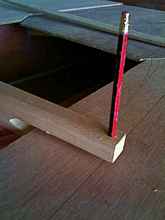
This is a very easily and quickly made tool
that will enable you to draw a line on a surface to match
a line which is below an oversized sheet, and therefore not
visible. In this case, oversized ply is laid where the cockpit
seats will be, over the curved vertical seat fronts. It was
handy to know where those seatfronts were relative to the
overhang while drawing the new edge. This photo shows the
tool from underneath. It has been shaped so that the end of
the bottom fork will touch the form that will dictate the
position of the pencil, above. It could equally be made to
draw a line a given distance in or out from the edge. |
|
The tool is just a 75 x 19 off-cut about 180
long, with a pair of saw cuts inside to make it into a two
pronged fork. The pencil is fitted into a tight hole and the
bottom fork trimmed and shaped to give the correct length.
Time to make this? About 4 minutes. |
 |
Because I want to keep moisture out of these
lockers/buoyancy compartments, I've decided to put the mast
step at seat level, rather than on the keelson. I could have
encapsulated the bottom of the mast in a tube, drained to
the cockpit, but preferred a simpler arrangement that will
also make stepping the mast a tiny bit easier. The compression
post is 33mm thick and is rebated into a 100 x 20 beam between
B2 and B3, with 20 x 20 doublers under the outside edges.
The step block will sit on the ply above all this. |

|
|
|
  |