|
|
| Building
Annie - A Navigator 15ft Yawl - Pt 3 |
| By Robert Ditterich - Geelong,
Victoria - Australia
|
 |
| To
Part One
To
Part Two
To Part Three
A Pictorial Essay of a Navigator
Build
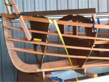
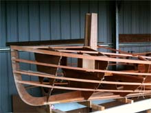
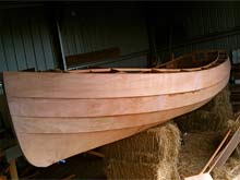
dry fitting gunwales
click images to enlarge
|
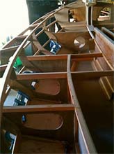
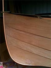
Here the two gunwales have been glued aft of the CB case, but are just 'waiting' at the bow end due to lack of a good stretch of time. I found it more useful to glue half of each rather than one complete side because I want to bring the bow ends together at the same time to avoid asymmetric tension or twist.
The forward ends are mainly stressed along the horizontal plane whereas the aft ends are mainly stressed in the vertical plane. There is a significant and sudden rise near the transom which is bending against the thickest (and therefore stiffest) dimension. To alleviate this I used a handsaw to cut down the middle of the gunwales back to B7 (about 900mm) so that the top and bottom sections of the gunwale could slide against each other to take up the sheer curve comfortably. It wasn't necessary to pull any similar tricks on the remainder of the 20 x 40 strip.
The cut surfaces were obviously wet out with unthinned epoxy before thickened goo was brushed in and then the clamps applied. |
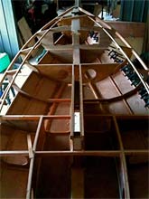
Considering the shear
|
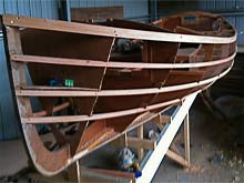
There is a hint of 'powderhorn' shape as the sheerline broadens on its way forward, and I've noticed this in many previous builds. I would prefer to minimise this if I can, and when it is time to 'nuance' (I know it's not supposed to be a verb) the gunwale shape we will see if it can be adjusted with the hand plane.
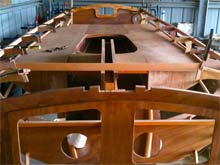
It is impossible to capture in a single picture the sweetness of some of these curves as you walk around them. In this picture, for instance she looks very long and thin, but the impression from above the centre board is of a broad, beamy and voluminous shape. I only hope I can do these lines the justice they deserve. I do love drawing, and this is just 3D drawing with stringers.
The interior suddenly looks much more spacious than I had expected too, since the gunwales went on. |
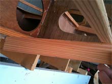
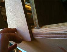
beveling the bottom stringer
|
This is a rather confusing pic, but here I'm holding a piece of oregon with its top edge touching the top outside edge of the bottom panel (where there will be a flush joint) and along to the bottom surface of the batten, which has been planed down, and is nearly ready to receive the hull panel. You can just see a small gap on the inside edge, that will be removed with a plane to finish the job. |
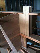
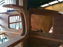
mocking up a tabernacle
|
very chunky at the moment, but I'm designing as I go to produce a tabernacle that is high enough to leave the boom attached when lowering the mast. Think it will work, but I do have misgivings about the extra bulk involved. The pieces here are untrimmed and will look more elegant I hope... |
tabernacle development
|
These are the oversized compression post pieces that will also form angled mast stops within the tabernacle. They are housed within the king plank.
Oversized top pieces overlap the lower unit providing strength and gluing surface area. |
|
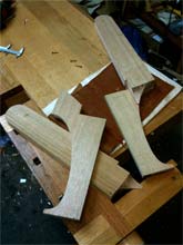
Bits refined for shape and weight reduction, ready for assembly. |
|
Still some bits missing here, and some slightly unfinished shapes. |
|
the gothic tabernacle support a good place, between the legs, for a novel or a map. |
planking begins
|
Cable ties hold the plank to the bottom sheet, and lots of clamps hold the top edge to the stringer. Getting the bottom curve right takes some careful fitting; it is more curved than you imagine when you begin, so leave a little extra depth in the plank to allow for adjustment of the inner edge. The top edge is dead easy because once the inner edge fits, a pencil line can be drawn along the stringer to mark its shape. |
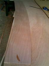
using plank as template for its opposite number
|
Having cut the first planks, I used them as templates. Now in a perfect world, the boat will be identical on both sides...a thoroughly symmetrical shape. But don't assume this will always be true! My starboard bottom plank needed to be about 2mm higher as it went past B#3 to be flush with the top of the stringer. Actually I was quite pleased with that.
This is Joubert Marine ply, supplied by Denman Marine in Tasmania. Very nice stuff it is too. |
preparing for the third row of planking
|
The third row (second from the top) is quite different from the lower planks. These are very much 'sides' and involve a different level of shaping for the bevels and the stringers. Here a scrap is held against the planed surface to test for flatness. Note how much material has been removed from the ply to achieve the 20mm overlap and the flat mating surface. In places these stringers have become almost triangular. |
first 'cutting of the gain'
|
Not particularly proud of this shot...work far from precision craft, but epoxy is a very sculptural medium, and form can be handled quite sculpturally with it. The stem shape will remain pretty rough until the boat is turned. Same with the edge of the plank and the gain itself. Incidentally the gains are being cut in the normal way, first with a handsaw cut along the bottom plank position, then a tapered rebate with a rebate plane, in this design John suggests 200mm from the forward edge.
Note at the top of the plank there is a scribed line 20mm from the top edge. For this you can use a variety of scratch or pencil depth gauges, or if you are careful, a pair of dividers. For this method to work the top edge of the plank has to be flat and flush with the top of the stringer, and you need to be happy with the line of the stringer too. |
dry fitting the long plank on the next run
|
This plank has been offered up, clamped, drawn, and its bottom edge extended by 20mm, faired with a batten, cut and then planed to preliminary fairness. The top edge is still a little oversized to allow for any loss of height in planing and fairing.
This plank was then used as a template for its partner on the starboard side. That board is cut to the fair bottom line and set aside for the moment. Clamps are still on the other side and so it remains un-angled and trimmed. Also, before gluing these boards I'll use them temporarily attached, finally to accurately dry fit the seat bases. |
more planking
|
I have found it best to use temporary bugle headed screws along the bottom of the planks, and clamps closely spaced along the top. You could easily use screws on top too if you were short of clamps, but then there will be more holes to fill carefully...
For a better initial finish, especially on the strongest curves, a scrap of ply along the line will even out the compression of the screws and leave a flatter edge. |
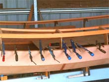
some people build boats because they like using clamps
|
...and some people use clamps because they don't like filling screw holes. |
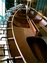
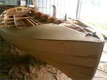
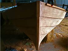
all planked
|
Having fitted the planks I am moving the hull down onto a lower height while it is still light enough to lift alone. Two hay bales first, then I'll lower her onto one bale each end, and maybe something firmer. |
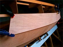
deck template
|
Here I'm using thin MDF sheet (came free as a cover sheet for some ply) as a template to work out the best use of my remaining ply. The template can be put onto a full sheet and moved around for most economical placement. The two foredeck pieces are nasty wasteful types of things, but can be nested up against each other for economy.
I did have a worry that this bow curve may end up assymetrical, given that I couldn't get a long view of the starboard side, but as it turns out, the template fits both sides and the symmetry is fine. |
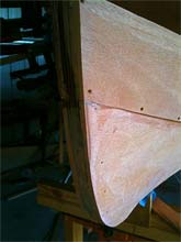
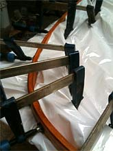
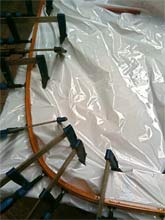
outer stem laminations
|
Only four strips on this one, I don't want a particularly strong outer stem visually. Blocks under the plastic sheet have been fixed at key points along an outline of the stem- traced way back when the stem was just finished. The tracing was onto a piece of 9mm ply off-cut. The blocks are all just scraps. |
|
The reason I want to fit the outer stem now is that I need to fit the bow D shackle before fitting the floor of the anchor well, and it has to be fitted before the king plank and fore deck...so I'll get the d shackle in soon while I can still access the back of the stem where the nuts will be....if you understood all of that you are probably nuts too. |
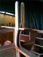
dry fitting outer stem
|
outer stem just held with one clamp at the top is a very good fit. The bottom aft edge will join the forward skeg. |
preliminary shaping of stem
|
Alright, the floor is a mess. The hay has almost all been fed out to the cows and the bits that are left need to be sorted to remove bits of boat....
I won't worry about the final shape of the stem until it is time to epoxy the hull. |
to be continued...
| If you are facinated by Navigator or just want to learn more about this exceptional boat, read Robert's book "Something About Navigator" |
 |

|
|
|
|